Monopile / transition piece
High-modulus annular load transfer, fatigue-oriented review, retained flow and a continuous high-lift pumping route.

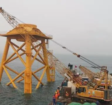
Offshore wind / Grouted foundation connections
Choose the grout around the connection, water exposure and installation route—then verify flow retention, strength, modulus, volume stability, pumpability and field quality control as one system.
Foundation and connection routes
These routes prevent an underwater infill material, a low-density bucket grout and a high-modulus structural annular grout from being treated as interchangeable.
High-modulus annular load transfer, fatigue-oriented review, retained flow and a continuous high-lift pumping route.
Geometry, seals, grout-line routing, return points, pump pressure and connection-specific strength and modulus.
Underwater anti-dispersion, cavity filling, flow retention, stable volume and a verified discharge or grout-return criterion.
Low grout mass, buoyancy review, long operational time and retained rheology through the planned offshore placement window.
Offshore grout selector
This is a screening matrix, not a substitution table. Open each product page to compare the stated requirement, published value, independent result and source.
| Product | Primary connection route | Evidence and decision focus |
|---|---|---|
| HGM-125 | Monopile, jacket and high-modulus annuli | 125 MPa-class requirement; initial/30/60-minute flow; high modulus |
| CBGM-125 | Monopile-transition piece and jacket connections | Requirements and independent results separated for strength, flow, modulus and tension |
| CBGM-130 | High-demand offshore annular connections | 130 MPa-class requirement with independently reported 28-day result |
| CBGM-50/70 | Submerged cavities and underwater foundation zones | Two strength grades; anti-dispersion, zero-bleeding and flow requirements |
| CBGM-C50 | Offshore infill and load-distribution cavities | C50-class infill route with independently reported flow and mechanical data |
| CBGM-5 | Suction bucket and caisson cavities | Low density, 4- and 8-hour retained-flow requirements and zero free bleeding |
First-hand offshore evidence
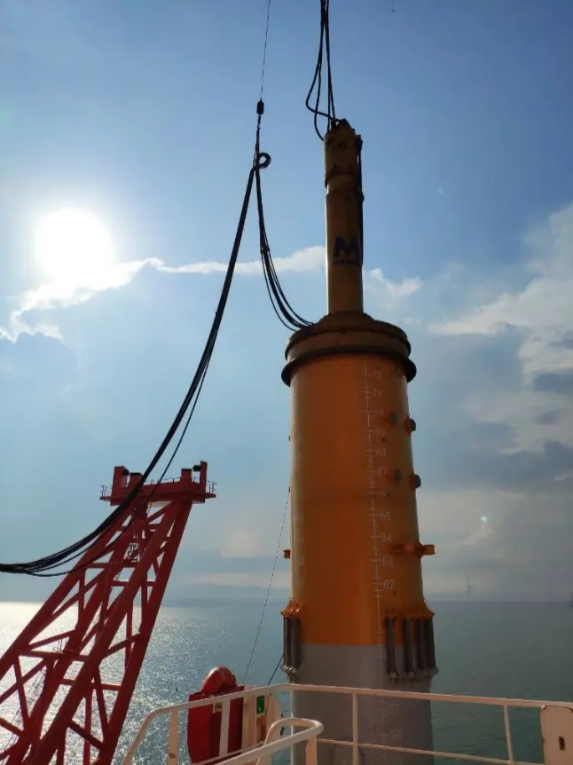
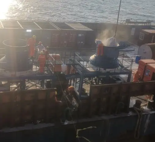
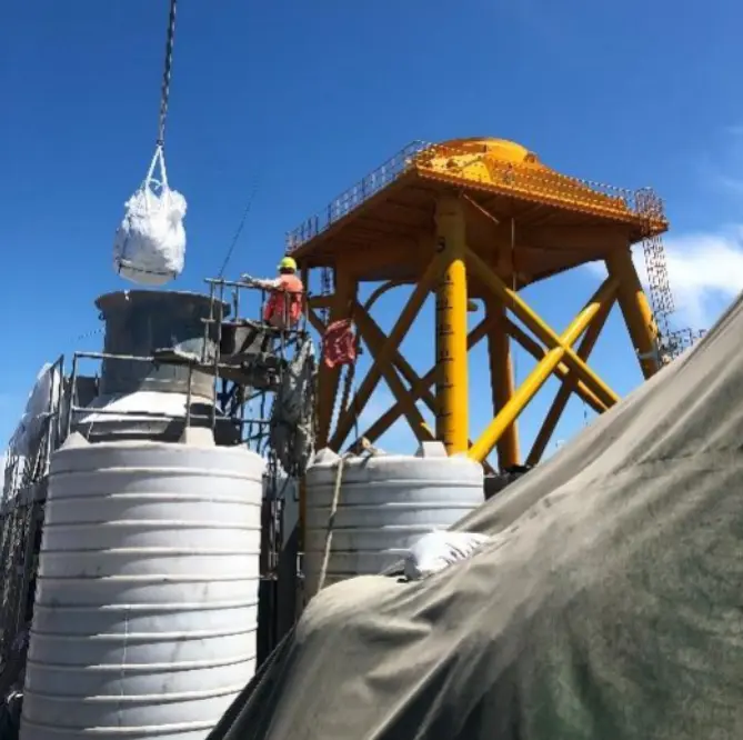
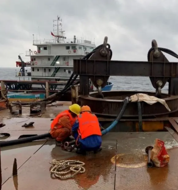
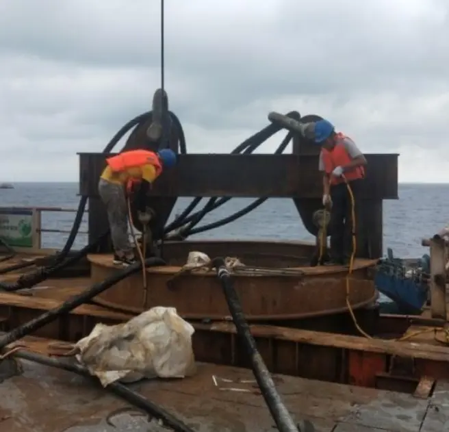
These photographs were selected from the supplied offshore wind business material. They illustrate the work environment and installation sequence; they do not replace a project-specific approval or method statement.
Offshore placement control
Field reliability depends on the interaction between grout rheology, production rate, hose pressure loss, lift, fill criterion and contingency capacity.
Confirm annulus or cavity limits, grout ports, vents, seals, return points and calculated volume.
Set mixer output, primary and standby pump capacity, hose diameter, length and pressure rating.
Calibrate water, mixing time, fresh density, air, flow and release to the pump.
Monitor flow, pressure, volume and the approved return or discharge criterion without interruption.
Record material batches, conditions, witnessed specimens, curing and test ages.
Document grout take, termination, pressure hold, curing, nonconformance and final acceptance.
Technical FAQ
The grout must be selected from the connection design, annular gap, specified strength and modulus, fatigue assessment, retained-flow window, temperature and pumping route. HGM-125, CBGM-125 and CBGM-130 are separate project-screening routes; none should be selected from strength alone.
No. Direct or submerged placement adds anti-dispersion, water movement, discharge visibility and placement-method requirements. CBGM-50/70 is positioned for underwater anti-dispersion applications, while HGM-125 and CBGM-125/130 address high-modulus annular load-transfer connections.
Provide the foundation and connection drawings, gap and volume, water depth and movement, acceptance table, temperature range, mixer and pump capacity, hose diameter and length, pressure limit, construction window, sampling plan and contingency route.
Public evidence separates specified requirements from reported results and removes laboratory, report, personnel, signature, stamp, QR-code, client and project-identifying information. The controlled report remains part of the private approval package.
Offshore wind technical review
We will screen the connection and installation constraints before recommending a grout route.